Networking part 3 - Network layers
Basics of networking III
- Network Layer: Overview
- Dataplane: Inside the router
- IP protocol
- Network layer: Control Plane
- Layer 3 - Intra-AS Routing in the Internet (OSPF)
- Inter-AS Routing: BGP
In the previous post, I have reviewed layers under application layer, like the transport layer. I will cover the Network layer in this post. While working with VPN and SSH projects, I have already studied a lot of basic ideas related to networking layers, but this layer is arguably the most complex layer in the protocol stack according to the author. A lot of the concepts covered in this chapter are very particular, probably not required to be studied deeply unless you are a network engineer. I will not cover all the details listed in the book, but it is still a good idea to observe some of the important ideas, so that I can have understanding of the topic.
Network Layer: Overview
The author divides the Network layer into two parts:
- Data plane (logics for individual router, determines how datagram arriving on router input port is forwarded to router output port)
Forwarding: Move packets from router’s input to appropriate router output
- Control plane (logics for network-wide control of the flow of datagrams, determines how datagram is routed among routers along end-end path from source host to destination host. )
Routing: Determine route taken by packets from source to destinationRouting tablefocuses on calculating changes in the network topology, includes entries of IPs to be used for text hop.
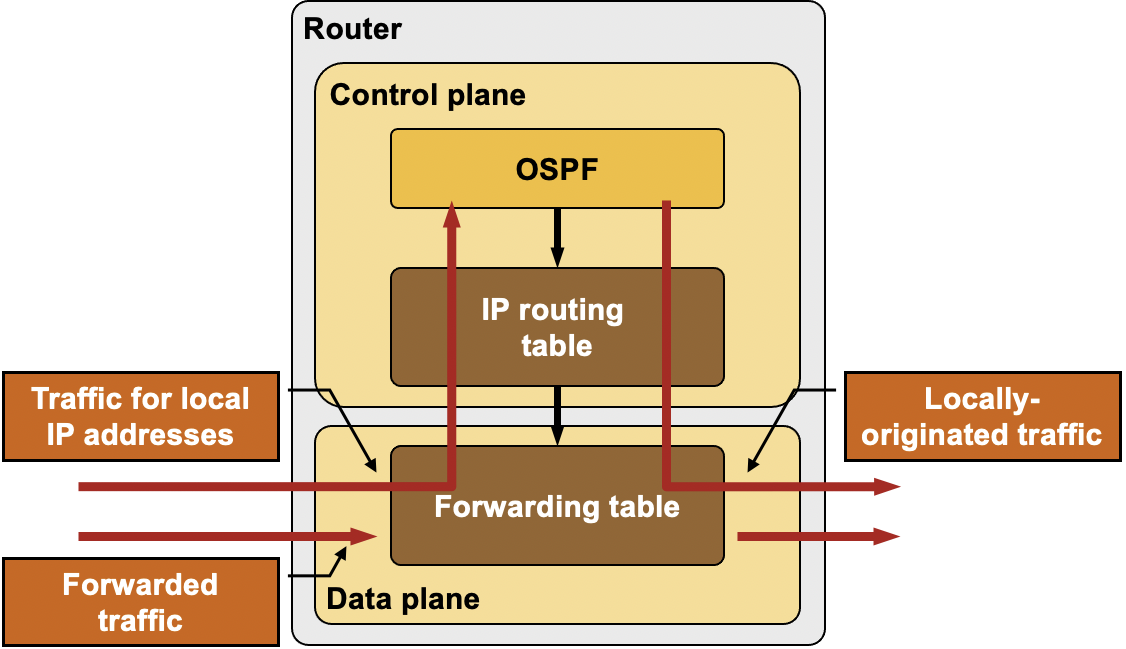
Some people use both terms (Forwarding, routing) interchangeably, but the author insists on clear distinctions b/w the two. Below is the summary of the most important ideas in the chapter
| Forwarding | Routing |
|---|---|
| Transfers the incoming packets from input port to the appropriate output port in a router. | Determines the route taken by the packets from source to their destination. |
| Uses the forwarding table. | Creates the forwarding tables. |
| Determines local forwarding at this router | Determines end-to-end path through network |
| Done in hardware at link speeds (very fast). | Done at time scales of minutes or hours. |
| Also known as “data plane”. | Also known as “control plane”. |
When routers connect to each other, a routing table is created for each of the connected routers. A routing table stores the destination IP address of each network that can be reached through that router. One of the important applications of a routing table is to prevent loops in a network. When a router receives a packet, it forwards the packet to the next hop following its routing table. A routing loop may occur if the next hop isn’t defined in the routing table. In order to prevent such loops, we use a routing table to stop forwarding packets to networks that can’t be reached through that router. This will be discussed further in the control plane section.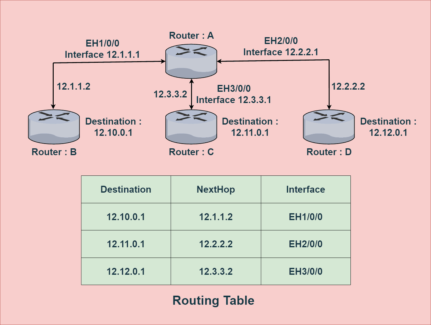
A forwarding table simply forwards the packets received in intermediate switches. It’s not responsible for selecting a path and only involves forwarding the packets to another attached network. It’s responsible of sending network data to its destination port (recall concepts we learned during SSH)
Where does Network layer belong in OSI model?
On sending side, segments are encapsulated into datagrams and sent to next router. On receiving side, you get the datagrams from upstream router, and deliver decoded segments to segment layer. Routers examine header fields in all IP datagrams passing through it.
But there are other service requirements that network layers should also fulfill:
Guaranteed delivery: This service guarantees that a packet sent by a source host will eventually arrive at the destination host.Guaranteed delivery with bounded delay: This service not only guarantees delivery of the packet, but delivery within a specified host-to-host delay bound (e.g, within 100 msec)In-order packet delivery: This service guarantees that packets arrive at the destination in the order that they were sentGuaranteed minimal bandwidth: This network-layer service emulates the behavior of a transmission link of a specified bit rate (for example, 1 Mbps) between sending and receiving hosts. As long as the sending host transmits bits below the specified bit rate, then all packets are eventually delivered to the destination host.Security: The network layer could encrypt all datagrams at the source and decrypt them at the destination, thereby providing confidentiality to all transport-layer segments.
Above are partial list of services that network could provide. But in practice, guaranteeing all above service requirements in the network layer is very difficult, often not possible, and that is why we implement complex error checking logic in upper layers.
Dataplane: Inside the router
Let’s take a look at Dataplane first.
Dataplane is all about forwarding datagrams to the router, thus it makes most sense to dig on the routers first. An important thing to understand is that routers are essentially a specialized computers. It has CPU and memory to temporarily and permanently store data to execute OS instructnions, such as system initialization, routhing functions, and switching functions.
Routers have Ramdom Access Memory (RAM) for temporary storage of IP routing table, Ethernet ARP table, and running configuration files. It has Read-Only Memory (ROM) for storing permanent bootup instructions. It has Flash drive for storing IOS and other system related files. A router of course does not have video adapters or sound card adapters. Instead, routers have specialized ports and network interface cards to interconnect devices to other networks.
In terms of networking, there are four router components that can be identified:
Input PortsSwitching FabricOutput PortsRouting processor

Input Ports
Let’s start from visiting what happens in the input ports.
- Firstly,
Line terminationreceives physical (analog) signals and turns them into digitial signals. Consider this as the reception stage. - Then,
data link processing layerdoes decapsulation of the data. - Next, the
Lookup, forwardinglayer checks thefowarding tableto see which packet should be forwarded to which output port via switching fabcric - Forwarding table is usuauly computed/updated by local routing processor, copied from remote SDN controllers or other network routers
- Once forwarding table decides which output port to direct the inputs, inputs get sent to the
switching fabric(or sometimes queued in the input port if router has scheduling mechanism).

Switching fabric
- Switching fabric is the connector b/w router’s input ports and output ports. This is a heart of a router, that pumps blood (inputs from input ports) to other organs (output ports).

- The actual process of
switching (forwarding)can take multiple different approaches. Switching via memoryis a older method where switching b/w inputs and outputs is directly controlled by routing processor’s CPU.Switching via a busis an approach where input port transfers a packet directly to output port over a shared bus, without intervention by routing processor, by prepending a switch internel label header to packets. All packets must cross single bus, so the switching speed is limited to the bus speed.

Switching via interconnection networkis an approach of overcoming the bandwidth of single bus, using something calledcrossbar, like how multiprocessor computer architectures work. The idea is quite complex, and it’s outside the scope of this research. Let’s just keep in mind that it exists.
Output Port
This is like the reverse of the input ports, as it takes packets that have been stored in the output port’s memory and transmits them over the output link.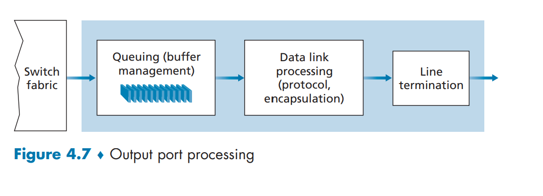
Similar to input port, queueing is often implemented to effciently resolve traffic load, and manage relative speed of switching fabric, line speed, etc. If the router’s memory gets exhausted, packet loss will occur as there is no more available memory to store arriving packets. This is how packets are “lost in the network” or “dropped at a router”. Again, specific queueing algorithms such as active queue management (AQM) or Random Early Detection (RED)within the router is out of the scope this blog post, so it will not be covered. Typical queueing strategies like FIFO (First in First out), round robin, and priority queues are used.
Routing processors
The routing processor performs control-plane functions (which will be discussed later). In traditional routers, it executes the routing protocols, maintains routing tables and attached link state information, and computes the forwarding table for the router.
IP protocol
Things like IPv4, IPv6, NAT, are topics that I have already covered across multiple other posts, like here. So to just fill up some of the gaps, length of IPv4 address are 32 bits, where each 4 decial numbers represent 4 bytes, (0-255).(0-255).(0.255).(0.255) - (in binary notation, something like 11000001 00100000 11011000 00001001). IPv6 will be 128 bits, but in this case, things like checksum is no longer required.
An interesting thing that can be noticed at this point is, Why does TCP/IP perform error checking at both transport and network layers? This is because:
- IP header is checksummed at the IP layer, while the TCP/UDP checksum is computed over the entire TCP/UDP segment
- IPv4 uses the checksum to detect corruption of packet headers. i.e. the source, destination, and other meta-data
- The TCP protocol includes an extra checksum that protects the packet “payload” as well as the header. So the entire thing!
- Checksum algorithms are identical for both
In terms of network interconnecting, group of hosts and router forms subnet.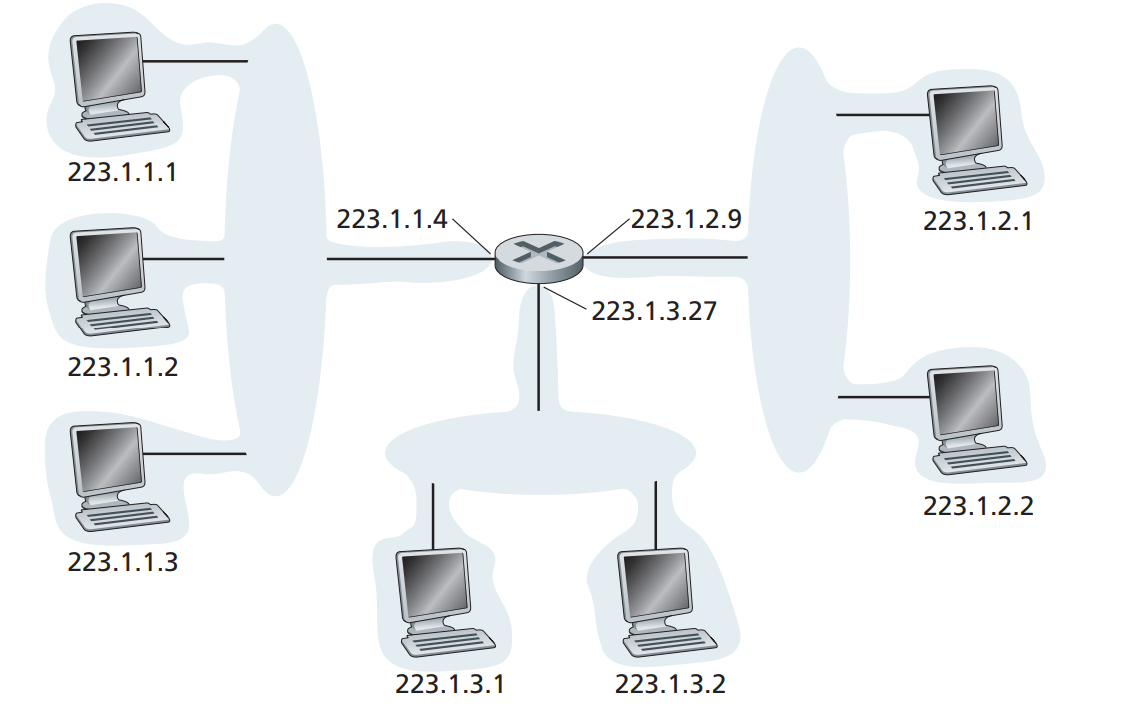
A router assigns subnet an internal IP address via subnet mask, and hosts attached to this subnet will follow the IP pattern of the subnets like the above figure. Hosts within the same subnet can talk directly to each other without having to go through routers, just like how we made the SSH connections via VPN.
Network Address Translation (NAT)
This is another familar concept. IPV4 is limited in terms of availability, and when routers assign hosts private IP addresses using things like Dynamic Host Configuration Protocol (DHCP), many hosts in the world will end-up with the same IP address, which makes it impossible for hosts to send and receive packets from the global Internet. NAT-enabled routers will allow hosts to access the internet via router’s public IP, and any responses coming back from the internet will hit router’s NAT translation table to direct the requests back to the hosts who requested.
Network layer: Control Plane
For the past few sections, we looked at the Data plane related concepts, which are things that’s happening within individual routers, at a more micro-level. Now it’s time to look at Control Plane, which deals with the macro, network-wide logic that not only controls how datagram is routed from one router to another, but also how each components and services are configured and managed. Control plane’s main idea is regarding routing algorithms, where routers find the “best route” to deliver data over the network, to minimize time delay and communication cost of packet transmission.
Network in routing can be described in the abstract graph representation, where we have nodes (object of interest) and edges (links that represent relationship b/w nodes), and we try to minimize costs while traveling from start node to end node.
Why do we have to select the paths in the first place? In the simplest data communication, the data is transmitted directly from the source node to the destination node. However, direct communication is usually impossible if the two nodes are far apart or in a difficult environment (congestion), so we need flexible and efficient routing algorithm to minimize various costs. Routing algorithms can be described in many ways. First of all:
Centralized routing algorithms: Computes costs based on global knowledge about the network, knowing all link connectivity prior to calculating the costs. Also referred to as link-state (LS) algorithms.Decentralized routing algorithms: Cost calculation is carried out in an iterative, distributed mannger by the router. No node has complete information about the costs, so it needs to iteratively exchange information within its neighboring nodes. Typical example is theDistance-vector (DV) algorithm.
Another way to classify an algorithm as static routing algorithms, where routes change very slowly over time, and Dynamic routing algorithms which the routes change dynamically when topology of the network or link costs change.
Finally, you can classify an algorithm load-sensitive algorithm, where link costs dynamically reflect the congestion level, or load-insensitive algorithms where link costs no not explicitly represent congestion level.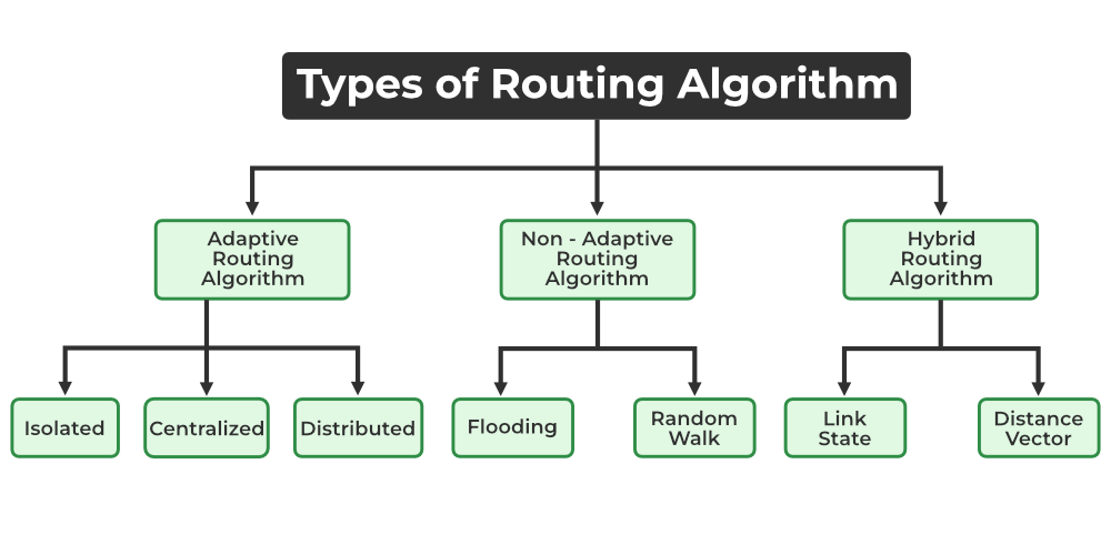
Hybrid Routing Protocol (HRP) is a network routing protocol that combines Distance Vector Routing Protocol (DVRP) and Link State Routing Protocol (LSRP) features. HRP is used to determine optimal network destination routes and report network topology data modifications. In the section below, I will give very general, high level overview of the two algorithms in the HRP category. Much of the stuff regarding actual algorithm logic, and complexity calculations, are beyond the scope of this post and will not be discussed.
Link-State (LS) Routing Algorithm (Dijkstra’s algorithm)
Initially, none of the nodes in the network have any information as to how many hops it would take to reach other nodes. So, to begin with, each node gathers information about its neighbours (nodes to which it is directly connected), and packages it into what is known as a link-state advertisement (LSA). Each node then advertises this link-state advertisement throughout the network, essentially telling all the nodes about its own connectivity info. In finality, every node in the network gets such ‘advertisements’ and therefore, now has a picture of the complete network.
Based on everyone’s LSA, each nodes draws pictures of the global network, and starts generating it’s own calculations (routing table) to reach specific destination node. After K iterations of calcuation, you can figure out least cost path to destination. Cost between direct links is denoted as \(C_{a,b}\), if not direct, this becomes infinity. Also, any time a link-state changes (it fails or a failed link comes up), the nodes involved in the link create a new LSA and broadcast it again to the whole network. Each node then runs the Djistra’s algorithm again to update its routing table.
The Distance-Vector (DV) Routing Algorithm (Bellman-Ford Equation)
Another important protocol is the decentralized DV routing algorithm, that is iterative, asynchronous, and distributed. The initial state is similar to LS algorithm. No nodes have picture of the network. But instead of gathering complete map using LSA prior to cost computation, each node receives some information from one or more directly attached neighbors, performs cost calculations, and then distributes cost calculation back to its neighbors. Furthermore, this iterative, distributive sharing process continues until no more sharing is required. Calculations are asynchronous, as each nodes do not depend on other calculations to finish their own calculations.
When a node running the DV algorithm detects a change in the link cost from itself to a neighbor, it updates its distance vector and, if there’s a change in the cost of the least-cost path, informs its neighbors of its new distance vector. The biggest difference with LS algorithm is that in LS, each node talks to all other nodes in the network, whereas in cases like DV algorithm, each node only talks to neighbor regarding it’s calculated costs.
Layer 3 - Intra-AS Routing in the Internet (OSPF)
Here is another very important concept in the control plane. Routers are like computers, and there are surely millions of them in the world. Expecting all of them to calculate DV or LS algorithms, and sharing and storing these calculations will require incredible amount of memory and time, and will not converge. One way to mitigate scalability problem, is to use something called Autonomous Systems (ASs). An Autonomous System (AS) is a set of Internet routable IP prefixes belonging to a network or a collection of networks that are all managed, controlled and supervised by a single entity or organization. The AS is assigned a globally unique 16 digit identification number一known as the autonomous system number or ASN一by the Internet Assigned Numbers Authority (IANA).
Imagine AS as town’s post office. Instead of every household figuring out how to deliver mails to another town, data packets cross the Internet by hopping from AS to AS until they reach the AS that contains their destination Internet Protocol (IP) address. Routers within the same AS all run the same routing algorithm and have information about each other. The routing algorithm running within an autonomous system is called an intra-autonomous system routing protocol.
Open Shortest Path First (OSPF)
OSPF is typical procedure to distribute IP routing information throughout a single Autonomous System (AS) in an IP network.
OSPF is a link-state routing protocol, that floods the AS by:
- Each router sends the information to every other router on the internetwork except its neighbors.
- Every router that receives the packet sends the copies to all its neighbors.
- Finally, each and every router receives a copy of the same information.
This picture is then used to calculate end-to-end paths through the AS, normally using a variant of the Dijkstra algorithm. Increasing the number of routers increases the size and frequency of the topology updates, and also the length of time it takes to calculate end-to-end routes, and that is why OSPF protocol is only ran within a signle AS. Similar to what we saw in the previous section, each router distributes information about its local state (usable interfaces and reachable neighbors, and the cost of using each interface) to other routers using a Link State Advertisement (LSA) message. Each router uses the received messages to build up an identical database that describes the topology of the AS.
Inter-AS Routing: BGP
The idea of Border Gateway Protocol (BGP) is straight forward. If OSPF is for Intra-AS routing, there must also be Inter-AS routing, and that is precisely what BGP is for. Destinations that are within the same AS, the entries in the router’s forwarding table are determined by the itra-AS routing protocol. But for Inter-AS routing BGP is used.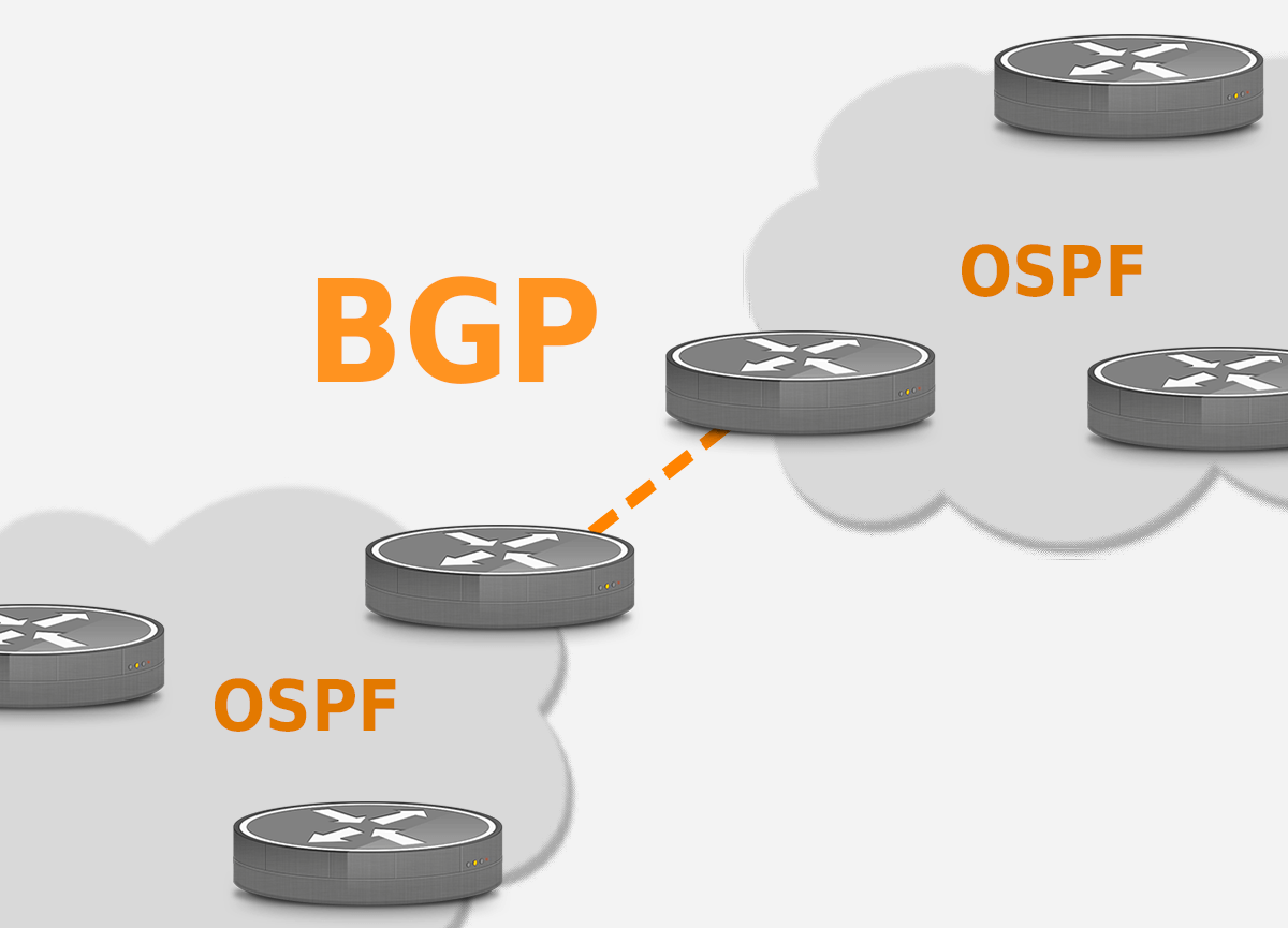
Since an inter-AS routing protocol involves coordination among multiple ASs, communicating ASs must run the same inter-AS routing protocol. This can be understood as how every country has its own languages, but to communicate with each other, they have to speak universal languages like English. In BGP, packets are not routed to a specific destination address, but instead to CIDRized prefixes, with each prefix representing a subnet or a collection of subnets 
- BGP connections b/w routers in the same AS is called
Internal BGP (iBGP)connection - BGP connections b/w different AS is called
External BGP (eBGP). - BGP would also have it’s own algorithm to determine best routes, how to hop between A/S while minimizing expenses, but this is outside the scope so won’t be discussed in detail.
There are a few other topics in the book for this chapter, such as SDN, ICMP, SNMP, NETCONF/YANG, and etc, but these will not be discussed here.


