Networking part 4 - Link/Physical layers
Basics of networking IV
- Layer 2 - Data Link Layer
- Layer 2 - Link Layer Addressing (MAC address, ARP)
- Physical Layer Transmission Medium
- Layer 1 - Digital Signals

Now this is far beyond the things I need to know, but it’s always to reach the end when you get started with something. Let’s briefly scratch the surface on the final bits to get full picture of networking.
Layer 2 - Data Link Layer
In the Data link layer,
Noderefers to any device (hosts, routers, switches, wifi access points) that runs link layer protocolLinkrefers to communication channel that connect adjacent nodes
Here, switch refers to: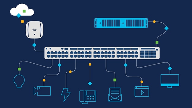
Routers and Switches are different. In simpler terms, the Ethernet switch creates networks and the router allows for connections between networks.
Link layer is literally about all the links that sits b/w nodes and how data travels b/w them.
Now let’s understand the flow of the data in lower layers. In the previous network layer, the best route to deliver a packet from source to destination over the network has been determined. Now the datagram will start moving through the links one by one, for example:
- Wifi link b/w sending host and wifi access point
- Ethernet link b/w access point and link layer switch
- A link b/w switch and the router
- A link b/w router to another router
- And from another router, a link b/w router and the ethernet link
- And finally a link b/w link and the server.
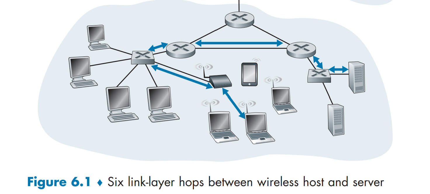
Although the basic service of any link layer is to move a datagram from one node to an adjacent node over a single communication link, there are few other things happening in this layer, such as:
Framing: Almost all link-layer protocols encapsulate each network-layer datagram within a link-layer frame before transmission over the link. A frame consists of a data field, in which the network-layer datagram is inserted, and a number of header fields. Will be discussed more later on.Link Access: A medium access control (MAC) protocol specifies the rules by which a frame is transmitted onto the link. This rules get more complicated when multiple nodes wait for frames from a single link, as it requires more coordination.Reliable Delivery: Reliable delivery features exists across all layers of OSI (e.g TCP). During link layer, you can enforce error detection, acknowledgments, retransmissions, although this is sometimes considered redundant and not implemented. The error correction is done at a bit-level, doing rudimentary checks like single parity bit check that counts even or odd number of bits.
Where is this implemented?
HTTP, TCP, and various other protocols are implemented on software side. Network layer has both software and hardware components. It depends on which link it is really. The Ethernet capabilities are either integrated into the motherboard chipset or implemented via a low-cost dedicated Ethernet chip. For the most part, the link layer is implemented on a chip called the network adapter, also sometimes known as a network interface controller (NIC).
- The sender’s controller in the PC takes the datagram generated from higher layers, encapsulate them to link layer frame, and then transmits the frame into the next communication link.
- The receiver’s controller receives frames (converted from bits), extracts the network layer datagram, performs error detection, and passes to upper layers.
Layer 2 - Link Layer Addressing (MAC address, ARP)
Datagrams have the source and destination, but to get to final destination, it must travel through various links. Yes, we know that receiver and sender would have network address, but what about the other links? Link layer addresses exists for all nodes.
In truth, it is not hosts and routers that have link-layer addresses but rather their adapters (that is, network interfaces) that have link-layer addresses. A host or router with multiple network interfaces will thus have multiple link-layer addresses associated with it, just as it would also have multiple IP addresses associated with it. A linklayer address is variously called a LAN address, a physical address, or a MAC address.
MAC address is embedded into every network card (known as Network Interface Card) in the hardware during the time of manufacturing, such as an Ethernet card or Wi-Fi card, and therefore cannot be changed. This is different from network level IP addresses that changes time to time. Simply put, MAC address is never public.
Remember in the link layer, links are only communicating b/w adjacent nodes. That means that your computer’s network adapter’s MAC address travels the network only until the next device along the way. If you have a router, then your machine’s MAC address will go no further than that. The MAC address of your router’s internet connection will show up in packets sent further upstream, until that too is replaced by the MAC address of the next device. So to reiterate, MAC address will never travel beyond your local network.
When an adapter wants to send a frame to some destination adapter, the sending adapter inserts the destination adapter’s MAC address into the frame and then sends the frame into the LAN. The next node receiving the frame will check if there is match in the MAC address. If there is a match, the adapter extracts the enclosed datagram and passes the datagram up the protocol stack. If there isn’t a match, the adapter discards the frame, without passing the network-layer datagram up. Thus, the destination only will be interrupted when the frame is received
Now, IP address and MAC address is two different addresses, but one must be translated to another via Address Resolution Protocol (ARP).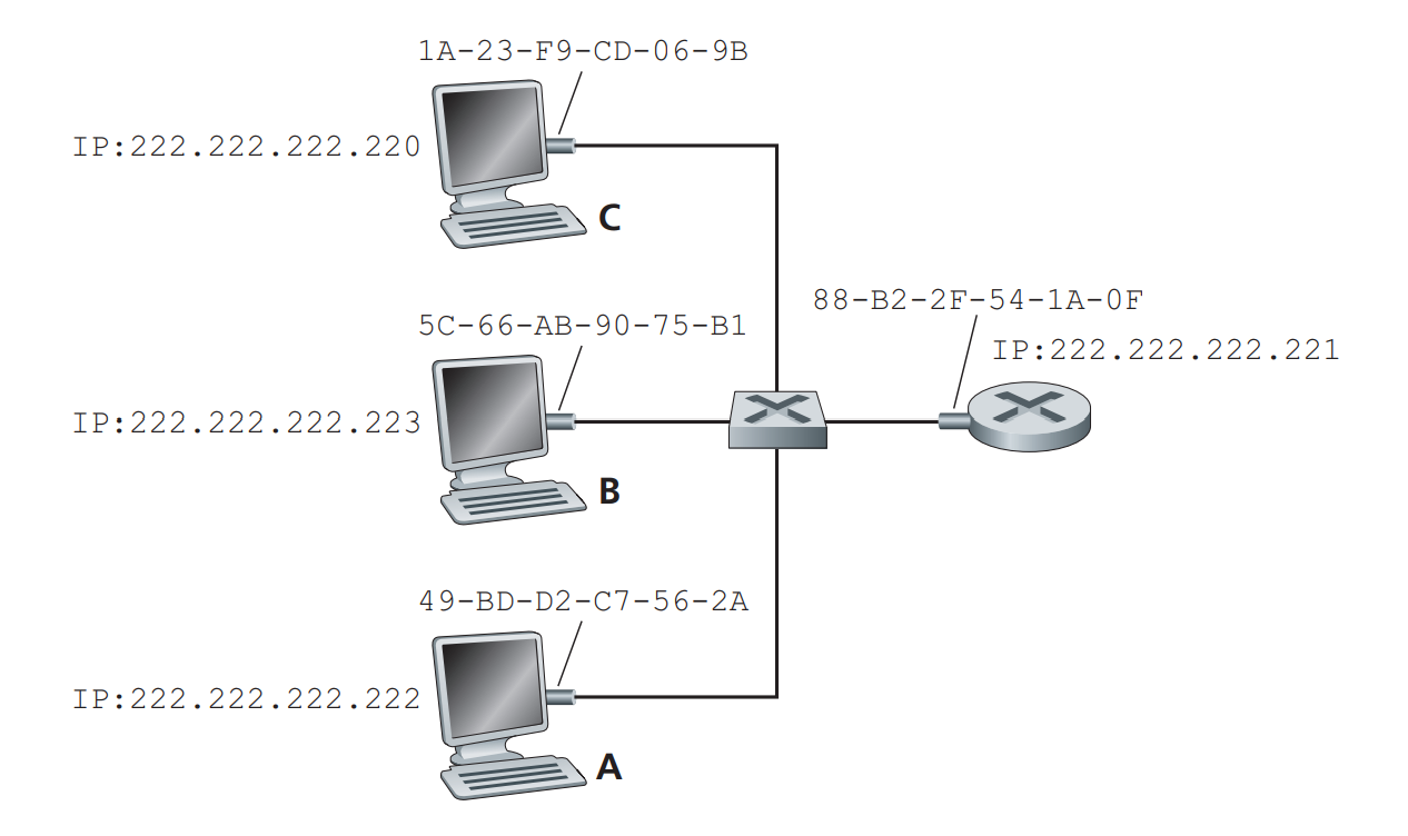
Suppose sender is 222.222.222.222. The sending adapter will then construct a link-layer frame containing the destination’s MAC address and send the frame into the LAN. An ARP module in the sending host takes any IP address on the same LAN as input, and returns the corresponding MAC address. Think of this as a key and value pair table. Obviously, ARP resolves IP addresses only for hosts and router interfaces on the same subnet. If a node in California were to try to use ARP to resolve the IP address for a node in Mississippi, ARP would return with an error — like how you are trying to access local variable globablly when coding.
Physical Layer Transmission Medium
Alas, we are at the final layer now. We are at the lowest level of OSI model at last. The physical layer in the OSI model controls how the data is transferred over the physical medium in a network channel. Frames from layer 2 is converted into network signals that can travel through the transimission medium, to reach the next “link” and ultimately the the final destination. Singals leaving the local network will eventually travel the long distance over below listed medium:
For guided transmission, there are:
Twisted Pair cable: two insulated conductors of a single circuit are twisted together to improve electromagnetic compatibility. These are the most widely used transmission medium cables. Cheap to install and operate, but lower bandwitch and susceptible to noises.Fibre optic cable: these are thin strands of glass that guide light along their length. These contain multiple optical fibers and are very often used for long-distance communications. Compared to other materials, these cables can carry huge amounts of data and run for miles without using signal repeaters. However, they are more delicate/fragile, and require more maintainence cost.Coaxial cable: Coaxial cables are made of PVC/Teflon and two parallel conductors that are separately insulated. Such cables carry high frequency electrical signals without any big loss. They are known for reliable and accurate transmission, high bandwidth and etc. But it gets expensive and needs to be grounded to prevent interference.
For unguided transmission media, there are:
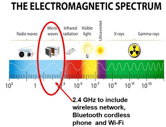
Radio waves: omnidirectional, sent waves can be received by any antenna, and travels unlimitedly. Can penerate barriers, but low data rate. Can be interferred easily.Infrared: These waves are useful for only very short distance communication. Unlike radio waves, they do not have the ability to penetrate barriers, but can send more data, and is more secure.Microwave: They comprise of electromagnetic waves with frequencies ranging between 1-400 GHz. Microwaves provide bandwidth between the range of 1 to 10 Mbps. Distance covered by the signal is proportional to the height of the antenna. Microwaves are essentially high-energy radio waves, and WI-FI is an example of microwave.
Layer 1 - Digital Signals
Lastly, the signals are converted into bitstreams to pass over the Transmission Medium. During digital data acquisition, transducers output analog signals which must be digitized for a computer. A computer cannot store continuous analog time waveforms like the transducers produce, so instead it breaks the signal into discrete ‘pieces’ or ‘samples’ to store them, so that they can recover the data and extract relevant information, validate it, and pass it back to the upper layers.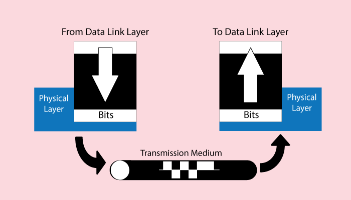
Understanding further in this domain is stepping towards Digital Signal Processing, which is definitely outside the scope of this blog posts, but it’s pretty interesting to read for sure.
